Video background credits: © NASA — Apollo archival footage, illustrative only.
With more than 40 student teams each year, C’Space is France’s largest student space-project competition. Hosting experimental rockets, mini-rockets and CanSats, universities and clubs compete to build as-real-as-possible launchers in order to carry out a genuine successful flight: reach maximum altitude and speed, gather data, then descend under parachute. All launches are overseen and evaluated by a panel of professionals — aerospace engineers, propulsion and safety specialists from CNES, plus scientific and project-management experts from Planète Sciences or associated institutions.
With more than 40 student teams each year, C’Space is France’s largest student space-project competition. Hosting experimental rockets, mini-rockets and CanSats, universities and clubs compete to build as-real-as-possible launchers in order to carry out a genuine successful flight: reach maximum altitude and speed, gather data, then descend under parachute. All launches are overseen and evaluated by a panel of professionals — aerospace engineers, propulsion and safety specialists from CNES, plus scientific and project-management experts from Planète Sciences or associated institutions.
National Student Launch Competition
National Student Launch Competition
CNES’s C’SPACE
CNES’s C’SPACE

The project
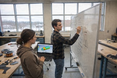
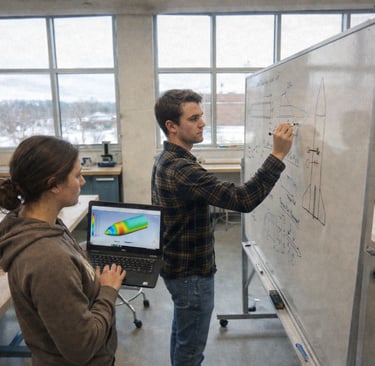
We are developing a solid-fuel rocket built around a carbon-fiber fuselage, a dual-PCB flight sequencer, and a Pitot-based sensing module designed to map pressure, velocity, and structural loads throughout ascent. The vehicle is engineered for a stable trajectory, a controlled parachute deployment using a custom servo-actuated bay, and reliable telemetry capture from liftoff to landing. Our ambition is to qualify the system for CNES’s C’Space campaign and produce a flight dataset precise enough to support aerodynamic and structural model validation.
The outcome
The project aims to demonstrate our ability to design, simulate, and build a flight-ready aerospace system within CNES’s national framework, positioning Arts et Métiers as a credible institution in student launch vehicle engineering. It is also intended to create a sustained technical presence for the school in the French aerospace ecosystem by delivering publishable flight data and a repeatable development pipeline. Finally, it serves to make hands-on rocketry and space engineering accessible to a broad cohort of students through open demonstrations, technical outreach, and cross-disciplinary involvement.

1) Preliminary sizing, mission definition, and stability model - done
We first defined the vehicle around a 110×114×2 mm carbon-fiber fuselage, a PLA nosecone with embedded static-pressure ports, and four fins sized from lift–static-margin curves presented in the project review. The ascent model incorporated the pressure distribution measured along the nosecone and expected Pitot-tube dynamic pressure errors quantified in the PPT (shape-induced bias). Static-margin targets follow CNES RCE requirements, validated through centre-of-gravity envelopes using measured component masses. Loads are estimated from preliminary thrust curves and the certified 5 kg nominal load at 4.6 m/s descent rate of the 152 cm parachute. This stage produces the stability dossier needed for RCE1/RCE2 acceptance.
2) Detailed CAD and internal mechanical architecture - done
We then completed full CAD of the nosecone with integrated nuts, sensor housings, and the threaded interface mating to the carbon tube, as shown in the PPT’s mechanical slides. The parachute case is dimensioned to the measured 396 cm³ packing volume, integrating vertical-stroke servo actuation and a retention latch to prevent premature release. Spring placement is set on the upper side of the trappe, matching the PPT design to ensure correct ejection geometry. All rings (Structural load-transfer ring, fixation rings) are modeled for PLA printing and later machining alignment with the carbon tube. This phase freezes every internal volume and cable path before manufacturing.
3) Avionics, sensing architecture, PCB routing, and calibration - done
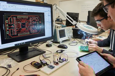
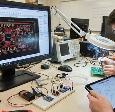
Afterwards, the flight sequencer was designed as a 150×80 mm, 2-layer PCB routed in EasyEDA with both manual and auto-routing steps, exactly as in the PPT screenshots. Breadboard tests validated the 9V→5V converter, switch logic, and all sensor interfaces before soldering. The Pitot tube was tested against the PPT’s documented shape-dependent static-pressure error, and its location on the fuselage follows the boundary-layer analyses shown. The electronics bay is CAD-fitted with stacked PCB–plateau mounting, ensuring clearances match the PPT integration diagrams. Calibration included pressure sensors, accelerometers, and strain-gauge amplification identified as “points durs” in the PPT.
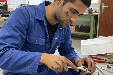
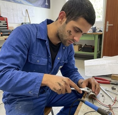
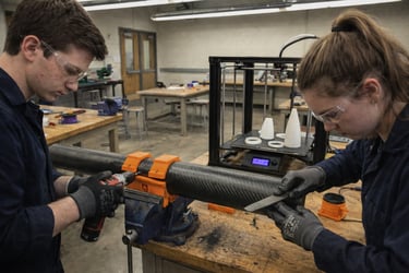
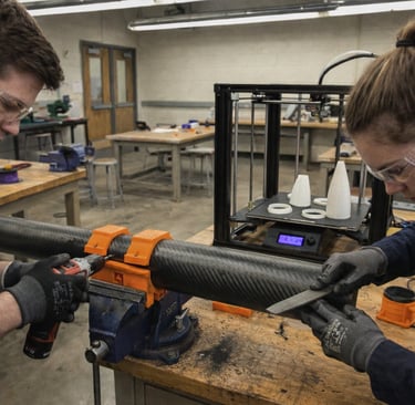
4) Manufacturing: carbon machining, PLA/3D printing, molds, and PCB assembly - in process
The 110×114×2 mm carbon tube is machined to open the trappe and drill the mounting holes using the 3D-printed molds displayed in the slides. PLA prints (nosecone, internal brackets, fixation rings, molds) follow the documented print-height limit of 40 mm, requiring segmented designs. The PCB is fabricated, partially soldered as shown, then fully assembled and inspected before electrical testing. The trappe, bagues, and carbon openings are adjusted for slip-fit tolerances using the printed molds as guides. This stage produces all physical components required for subsystem testing.
5) Ground testing, subsystem validation, and CNES RCE milestones - upcoming
Finally, we will have to validate parachute deployment by testing the servo-retention system, spring ejection, and latch integrity exactly as illustrated. Pitot–static readings are compared with theoretical error curves from the PPT to confirm acceptable bias before flight qualification. Sequencer tests include trigger logic, timestamping, and sensor data recording/decoding per RCE3 expectations. Mechanical tests check the trappe rotation lock, parachute-case volume conformity, and resistance of PLA–carbon interfaces. All results will feed the SCAE documentation required for CNES pre-qualification.
6) Final integration, full-stack testing, and flight readiness - upcoming
All assemblies—carbon tube, PLA nosecone, parachute case, trappe, rings, PCBs, and cabling—will be integrated per the PPT’s “mise en position” diagrams. We will perform an end-to-end dry run of the flight sequence: ignition logic, sensor polling, data logging, and recovery actuation. Final CG will then be re-measured with installed electronics and parachute to validate the stability margin derived in Stage 1. A structural inspection verifies the integrity of machined carbon areas and PLA components under load. The team will prepare the complete flight-readiness package for CNES inspection at Ger.
7) Launch campaign, flight operations, and data exploitation - upcoming
On site at the 1er Régiment des Hussards Parachutistes (Ger, 65), we proceed with CNES safety checks, pad integration, and final arming procedures. Post-launch recovery retrieves the airframe for immediate structural inspection and sensor-data extraction.
Pressure, velocity, and acceleration traces are matched against pre-flight simulations to assess nosecone port behavior and Pitot accuracy. Structural-load measurements are compared to the PPT’s predicted deformation-gauge requirements. A complete mission report is uploaded to SCAE and prepared for dissemination at school-level and national events.
The stages: where do we currently stand?

contact@amspace.fr
+33 650345244
Contact Us
Follow us
151 Boulevard de l'Hôpital, 75013 Paris, France